Industry Insight - Machining

Machining: The Foundation of Modern Manufacturing

Have you ever wondered how the countless metal products around us—from tiny screws to massive industrial equipment—are created? Behind this lies a precise technology: Machining.

What is Machining?


In simple terms, machining is the process of shaping a block of metal material into the desired shape and size using various tools and machines. Imagine you have a piece of clay that you can mold into different shapes; machining is like the metal version of molding clay, except we use much more precise tools and harder materials.

Diverse Machining Methods

There are many ways to perform machining, each with its unique advantages and applications. Here are several primary machining services our company provides:
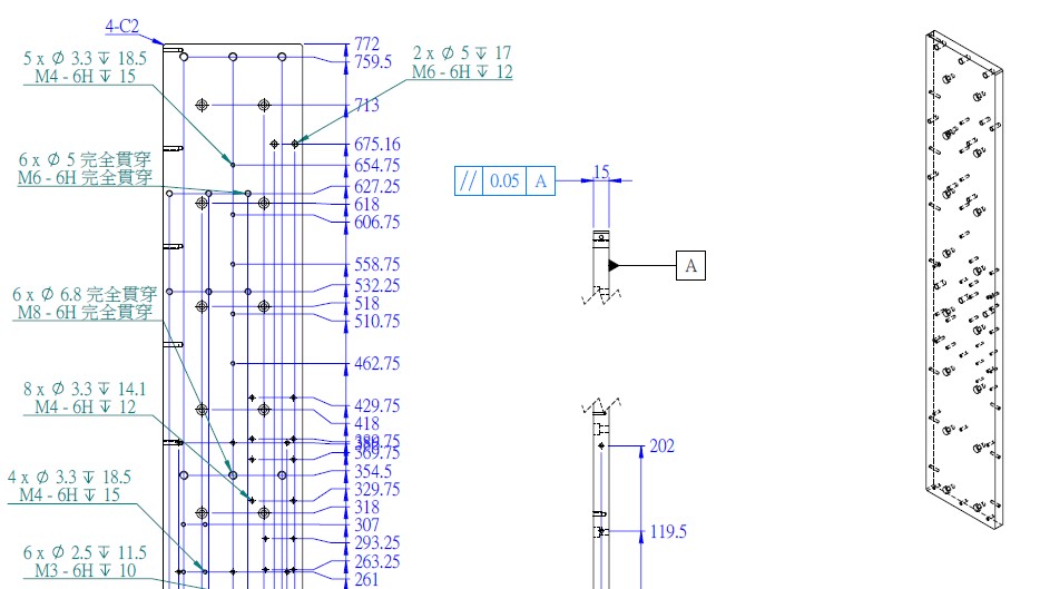
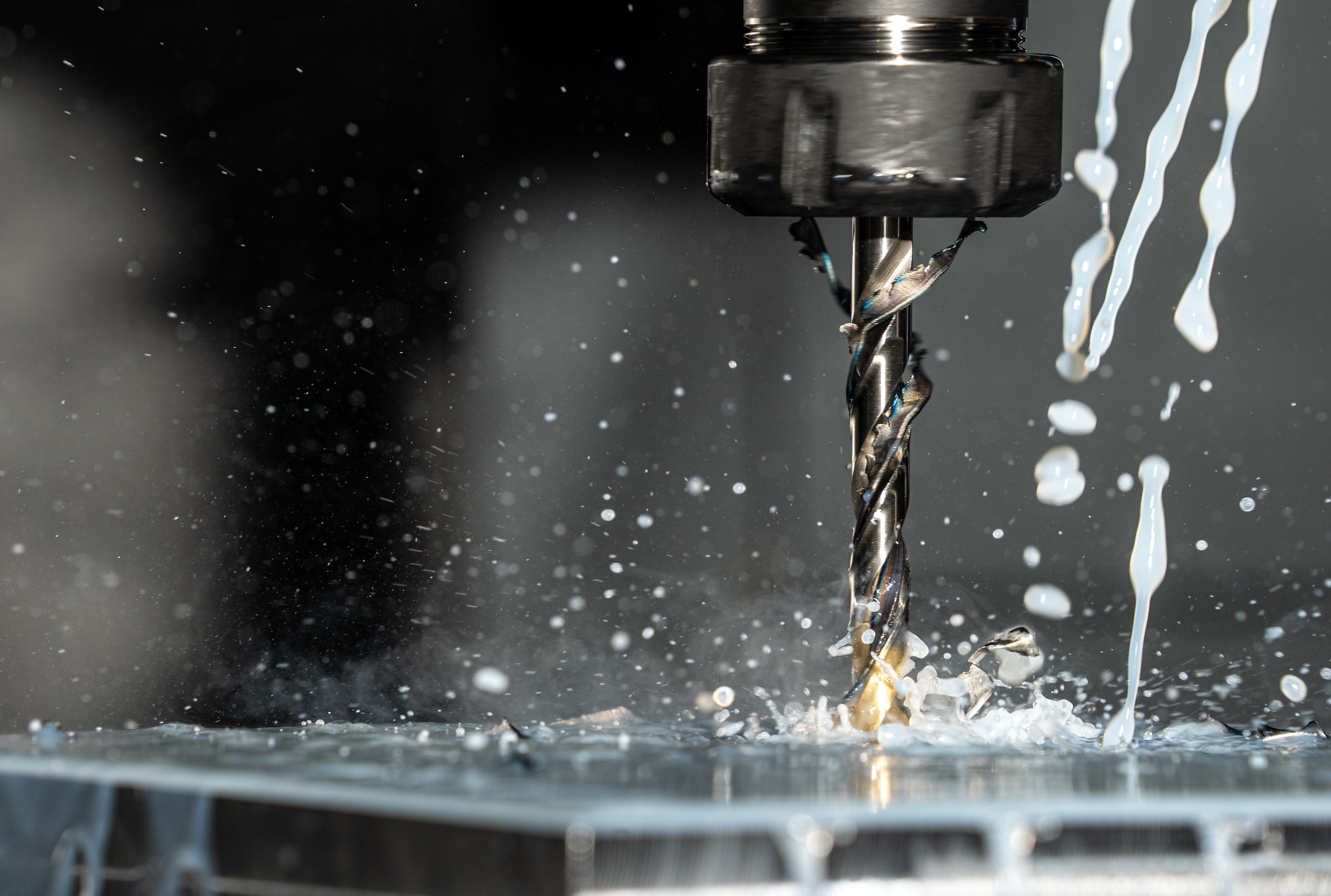
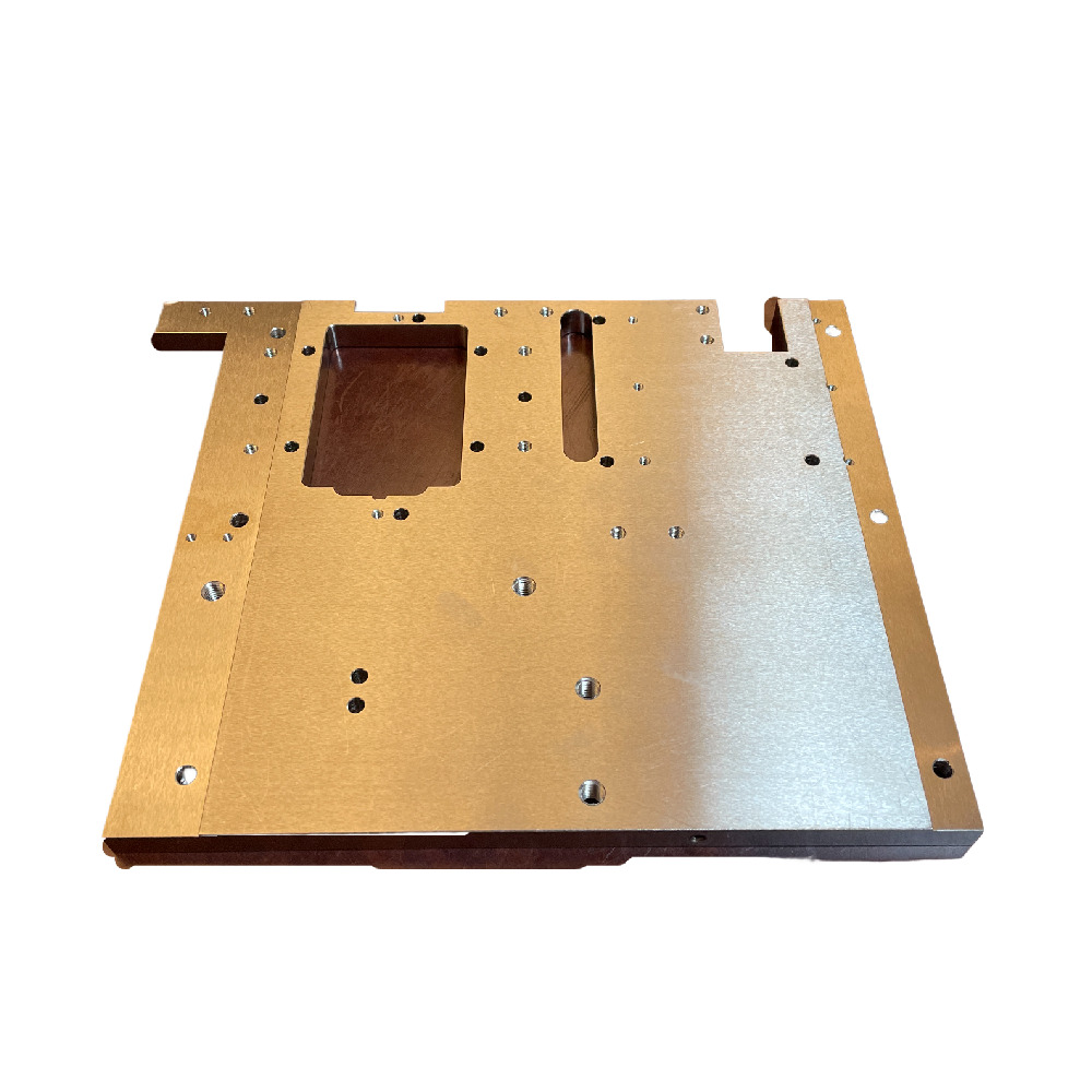
(1) Milling

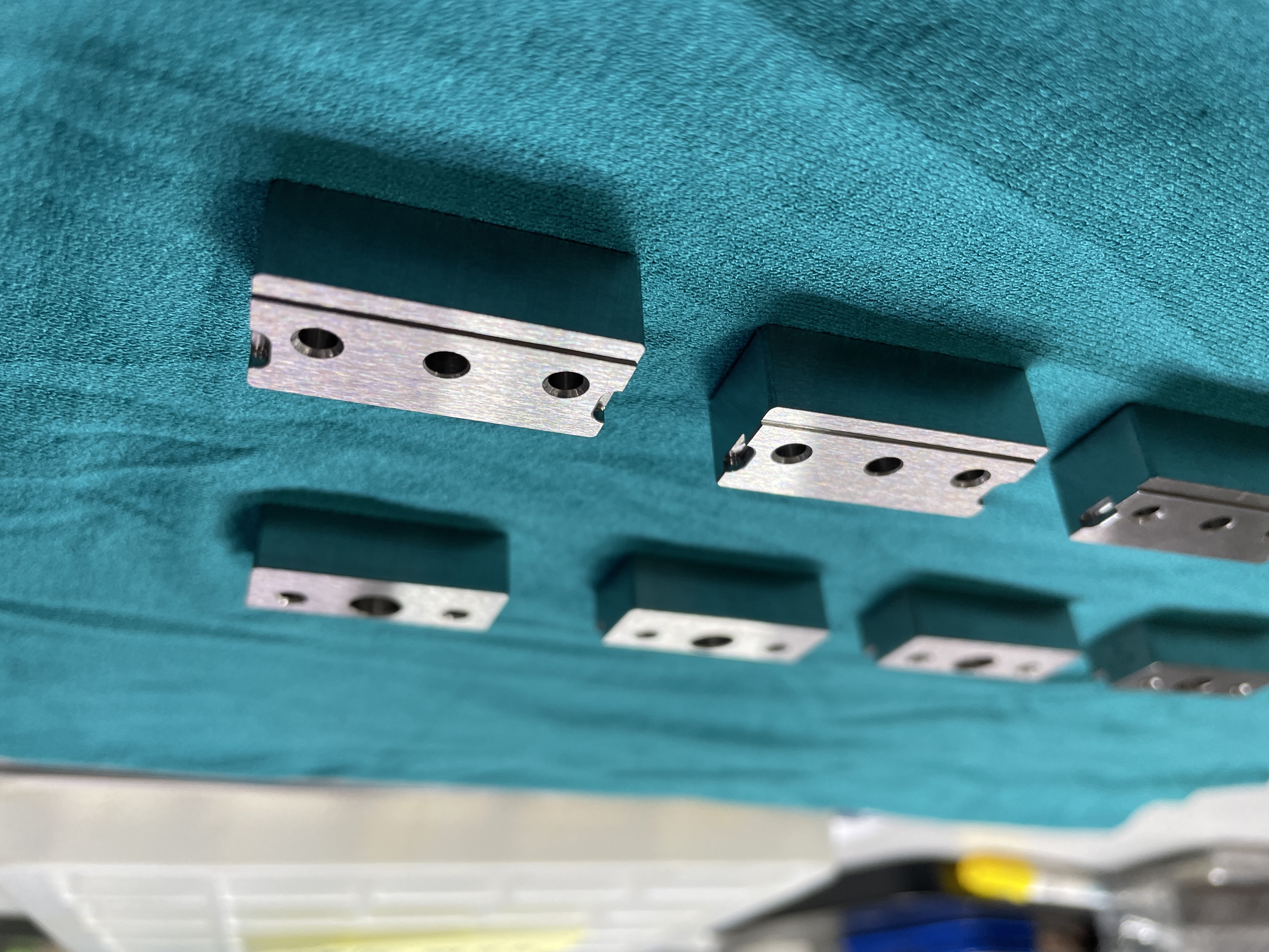
Milling is a versatile machining process suitable for cutting flat surfaces, slopes, grooves, or other geometric shapes. Milling machines use high-speed rotating cutters, typically made of high-speed steel or carbide, possessing extreme hardness and wear resistance. Milling is commonly used to manufacture complex parts requiring high precision, such as mechanical components.

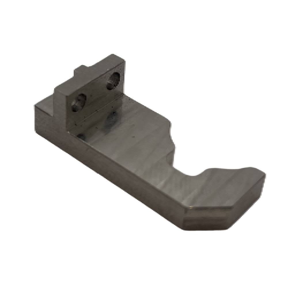
Case Study: We frequently machine mechanical components or fixtures for clients, transforming raw rectangular metal blocks into precise products through multiple cutting and flipping processes.
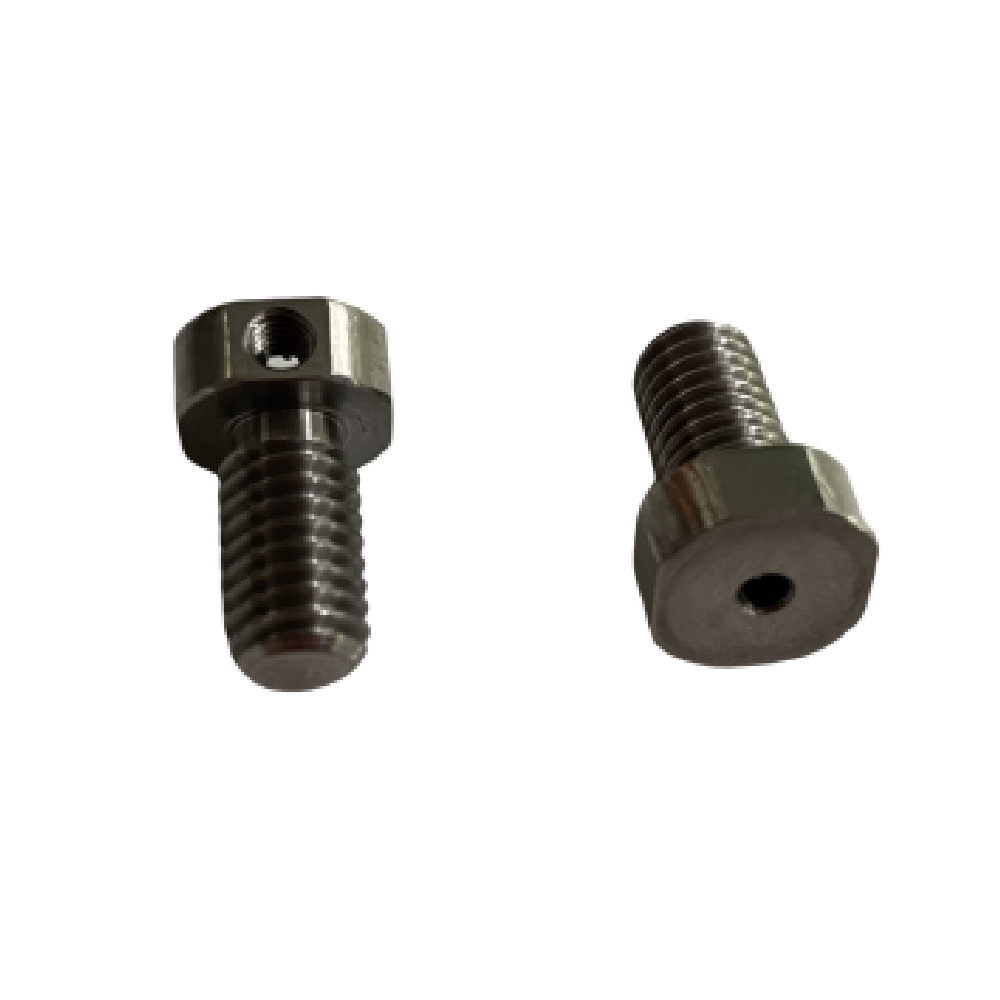
(2) Turning

Lathes are among the oldest and most commonly used machining equipment, primarily used for processing rotationally symmetrical workpieces. In the turning process, the workpiece is fixed on a rotating spindle, and the cutting tool moves linearly along the workpiece to remove material and form the desired shape. Common turning operations include outer diameter (OD), inner diameter (ID), facing, and threading. Turning is efficient and precise, suitable for manufacturing shaft and disk parts like bearings and screws.

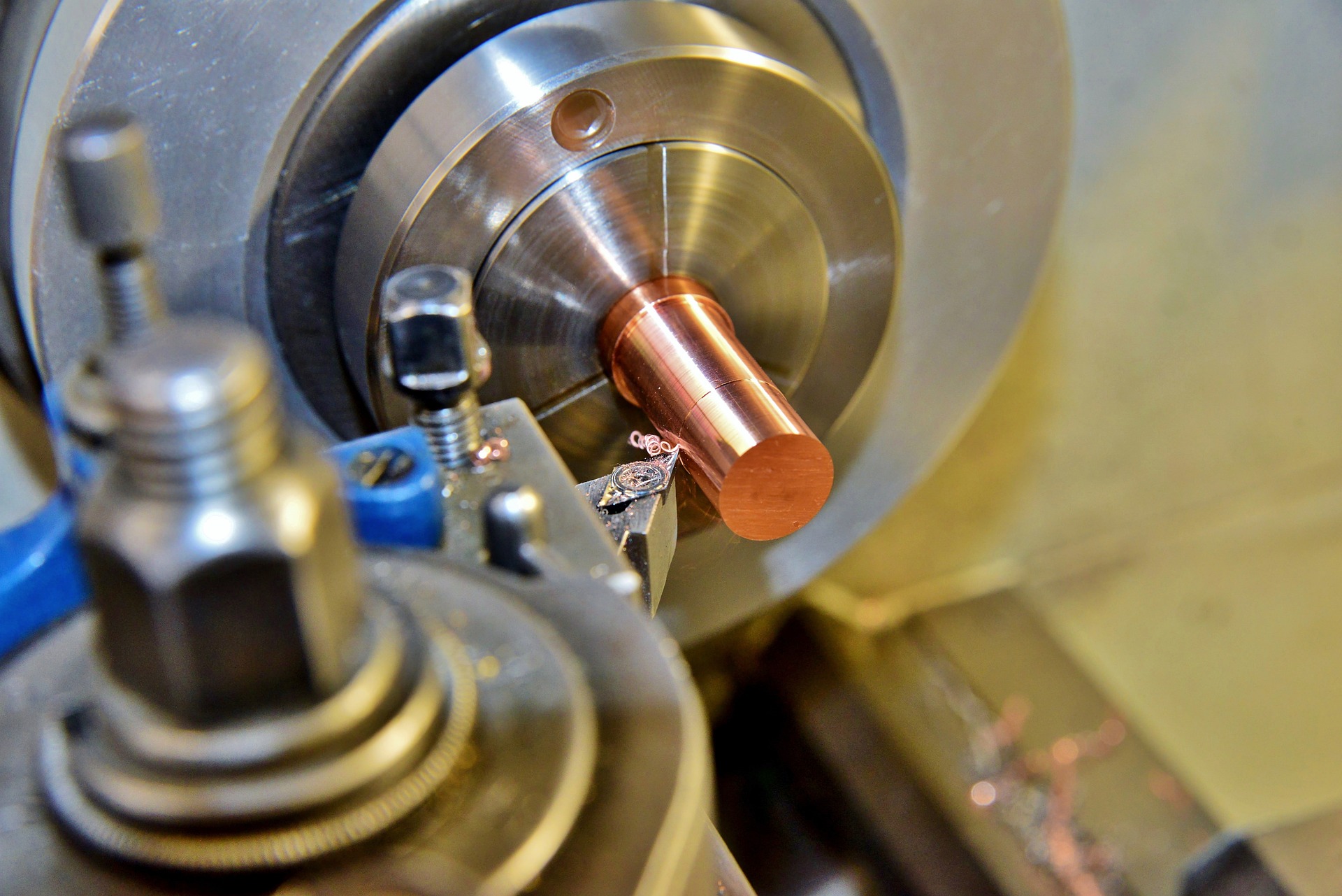
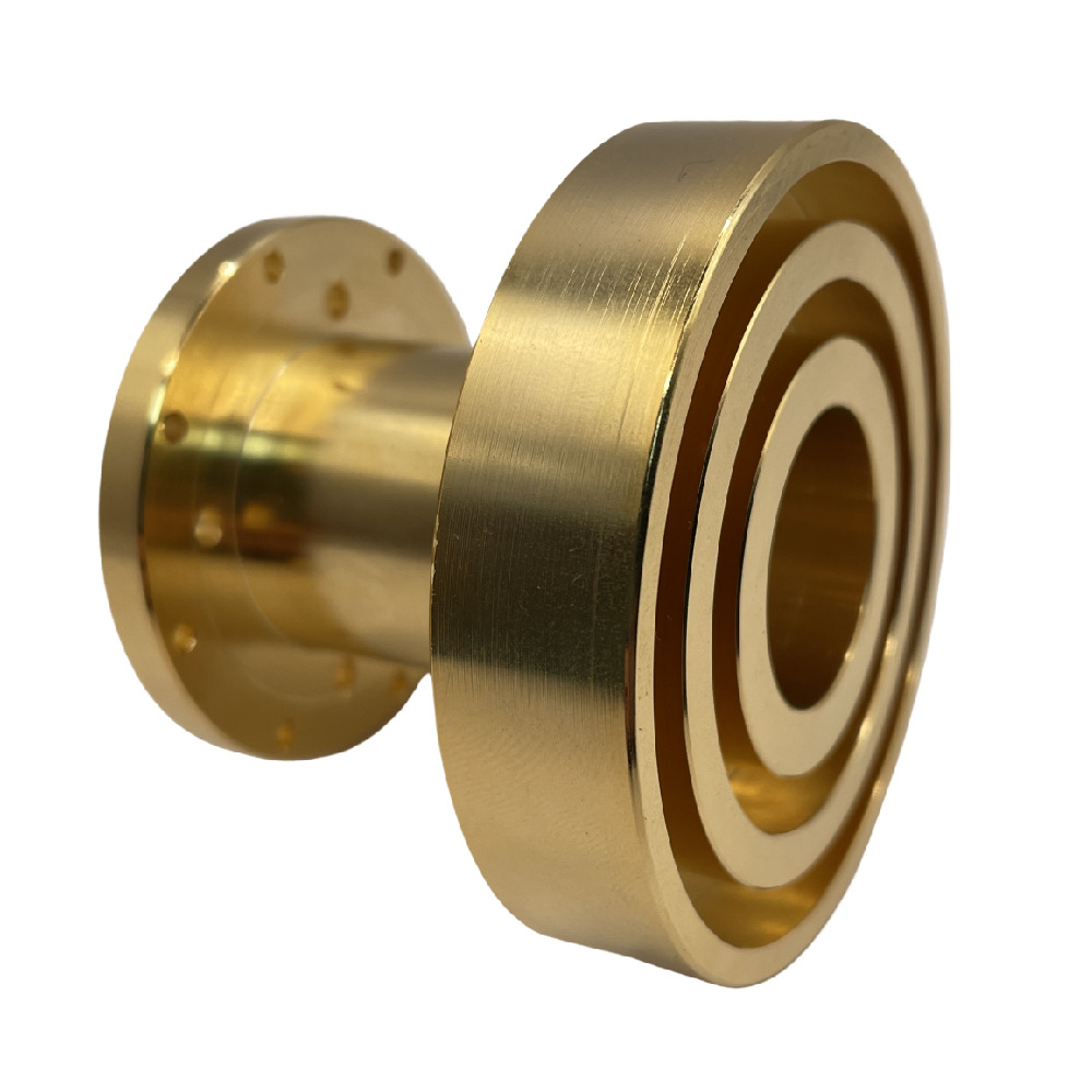
Case Study: Our turning technology can precisely shape a standard cylindrical bar into various functional components.

(3) Grinding

Grinding is a precision machining process that uses an abrasive wheel as a cutting tool to remove material from the workpiece surface, achieving high precision and low surface roughness. This process is commonly used for parts requiring extreme flatness and fine finishes, such as bearings and mechanical seals.

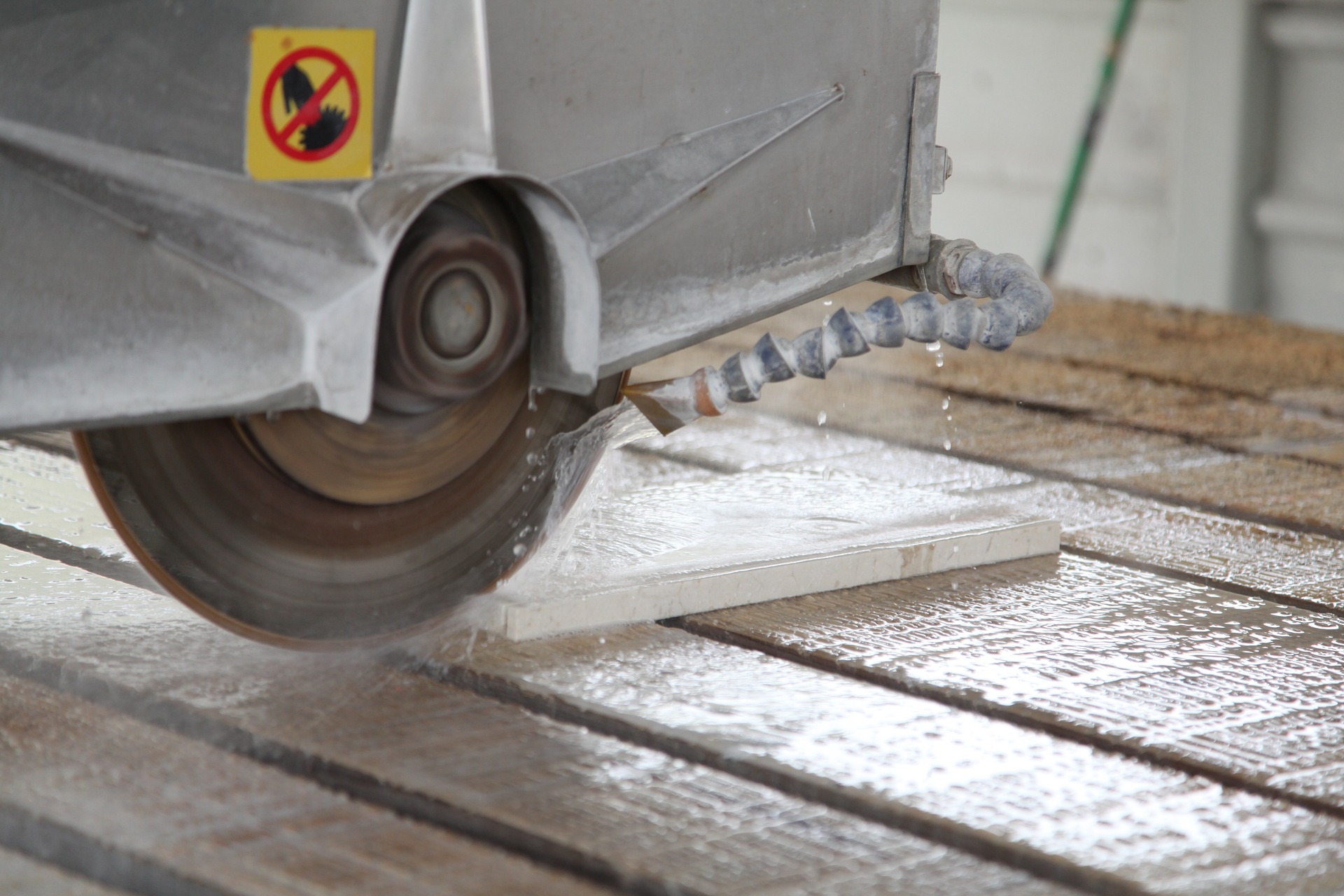
Case Study: CNC milled products processed by us achieve superior flatness and precision after undergoing grinding.

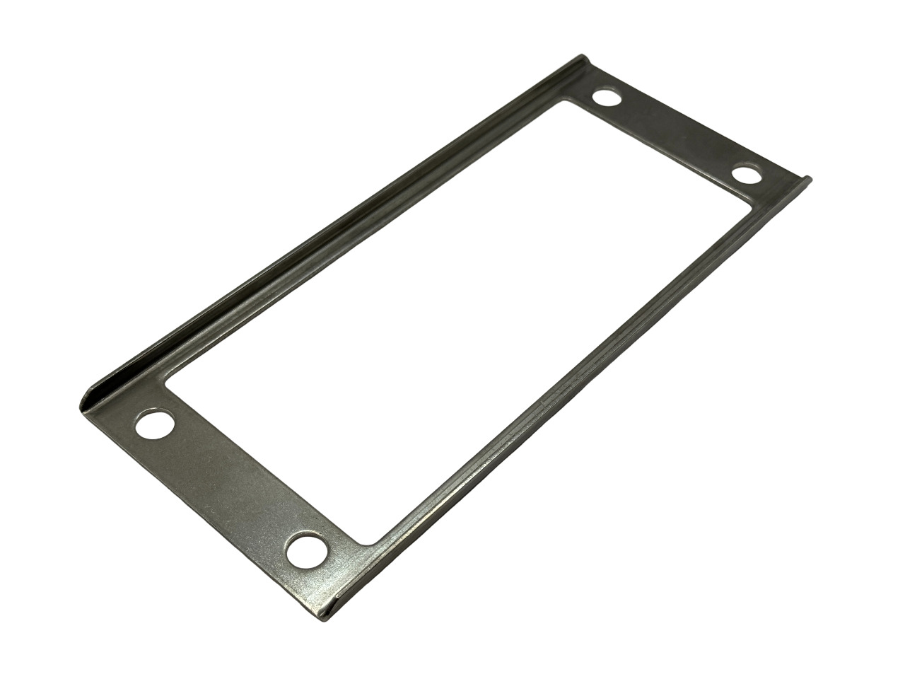
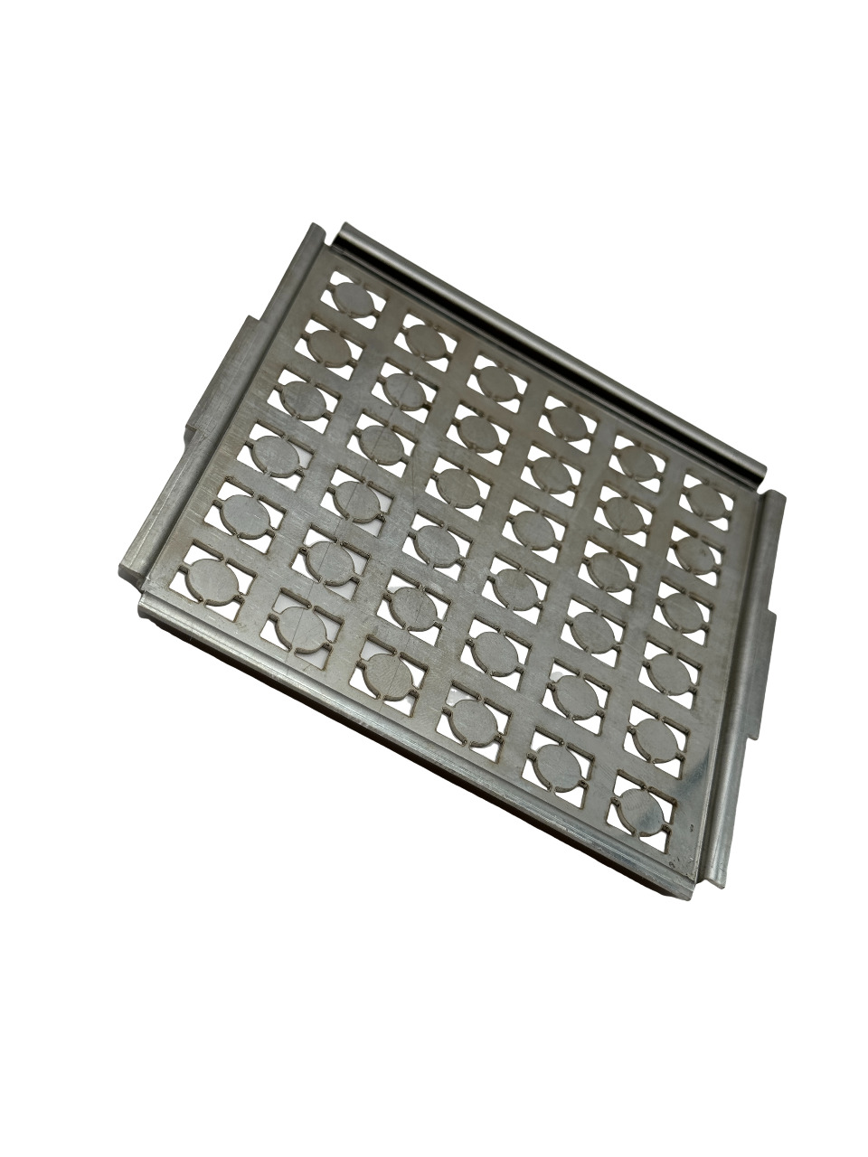
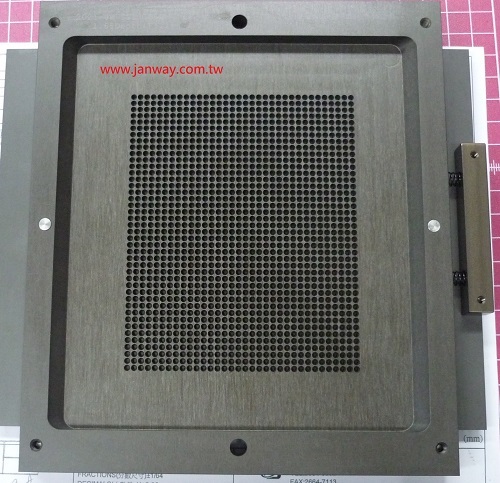
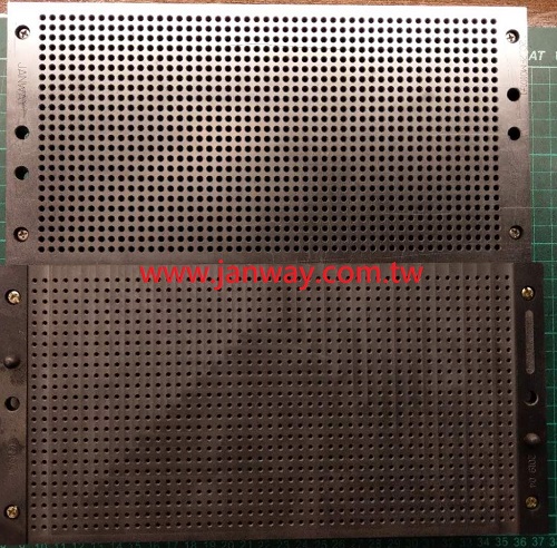
(4) Sheet Metal Working

Sheet metal working mainly involves processing thin metal sheets, usually involving cutting, bending, stamping, and welding. This method is widely used in automotive, appliance, and aerospace industries. Its advantage lies in the rapid, mass production of complex-shaped yet lightweight parts.

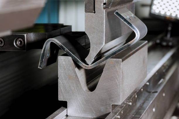
Case Study: We produced thin-plate fixtures for a client, successfully creating structurally sound and lightweight products using laser cutting and bending machines.

(5) Electrical Discharge Machining (EDM)

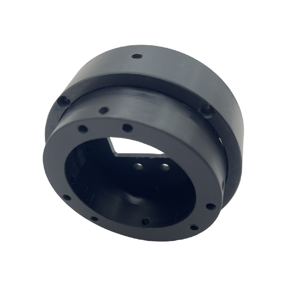
EDM is a machining method that removes material through electrical discharges from an electrode. It is primarily used for processing high-hardness materials that are difficult to machine mechanically. The EDM process uses the high temperature generated by the discharge to melt and remove metal, making it suitable for creating complex molds and high-precision parts.

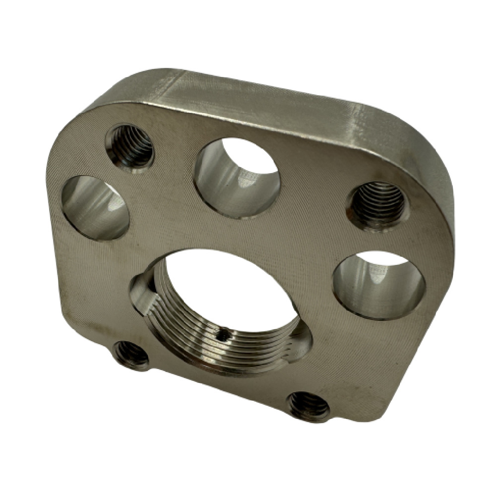
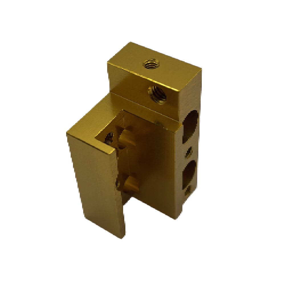
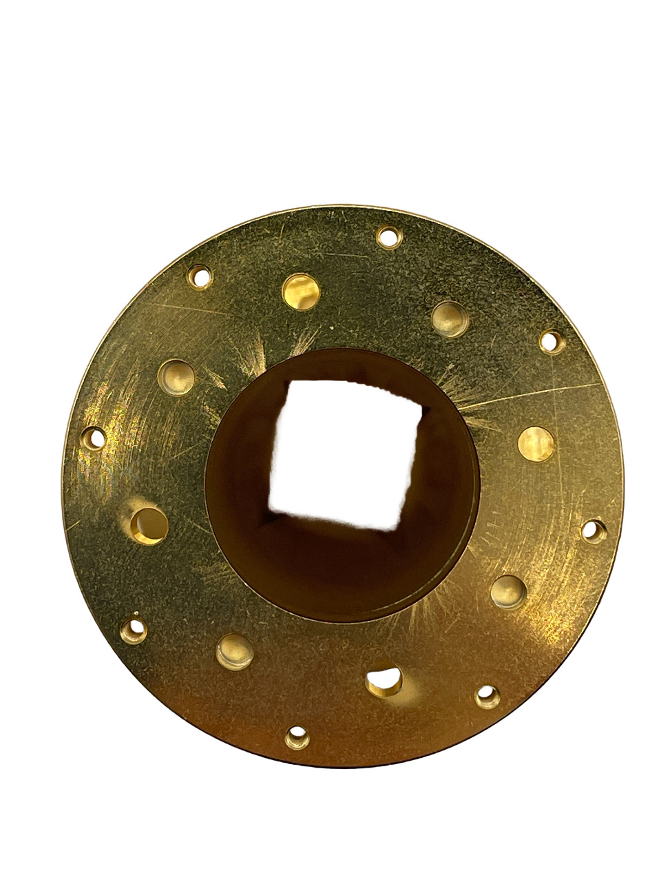
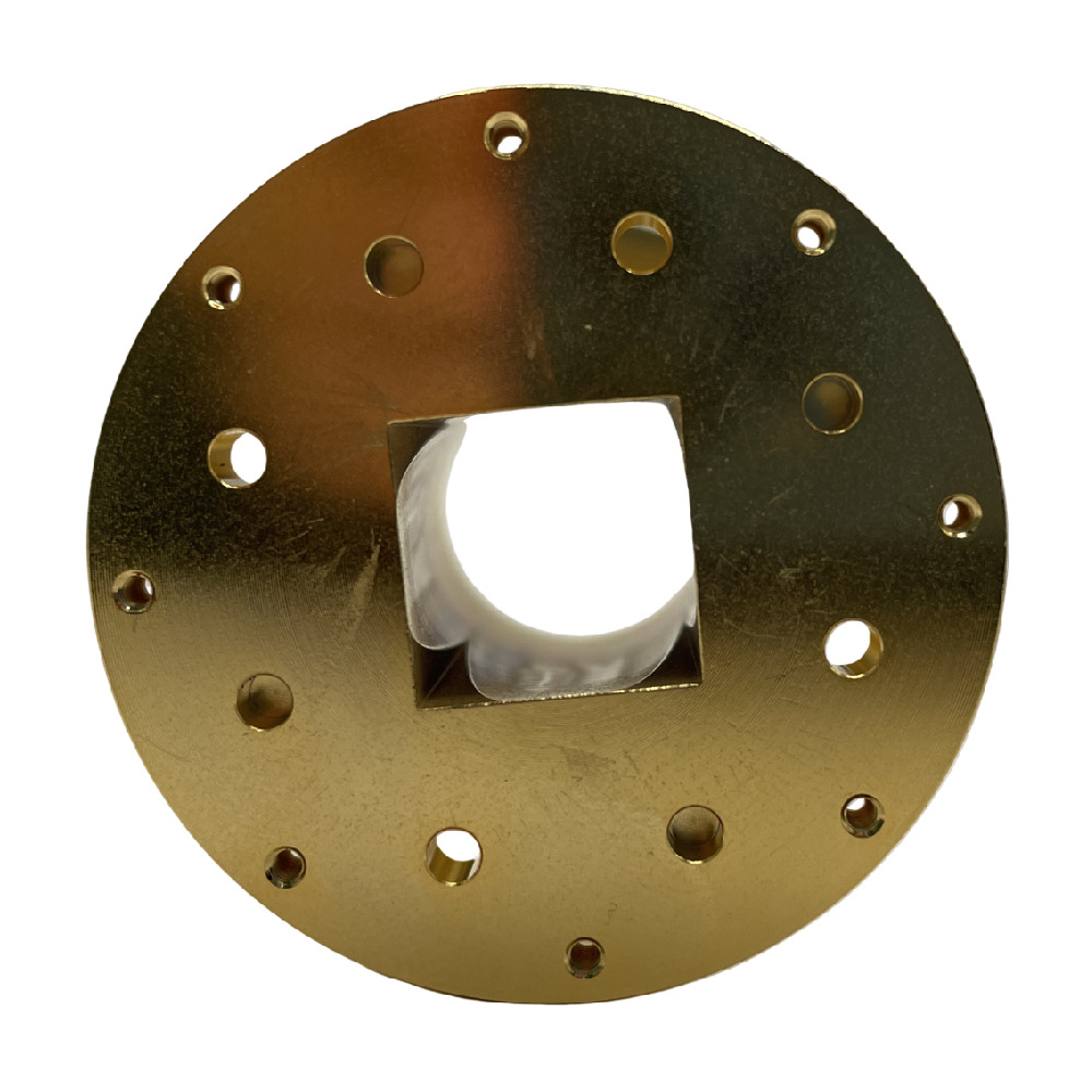
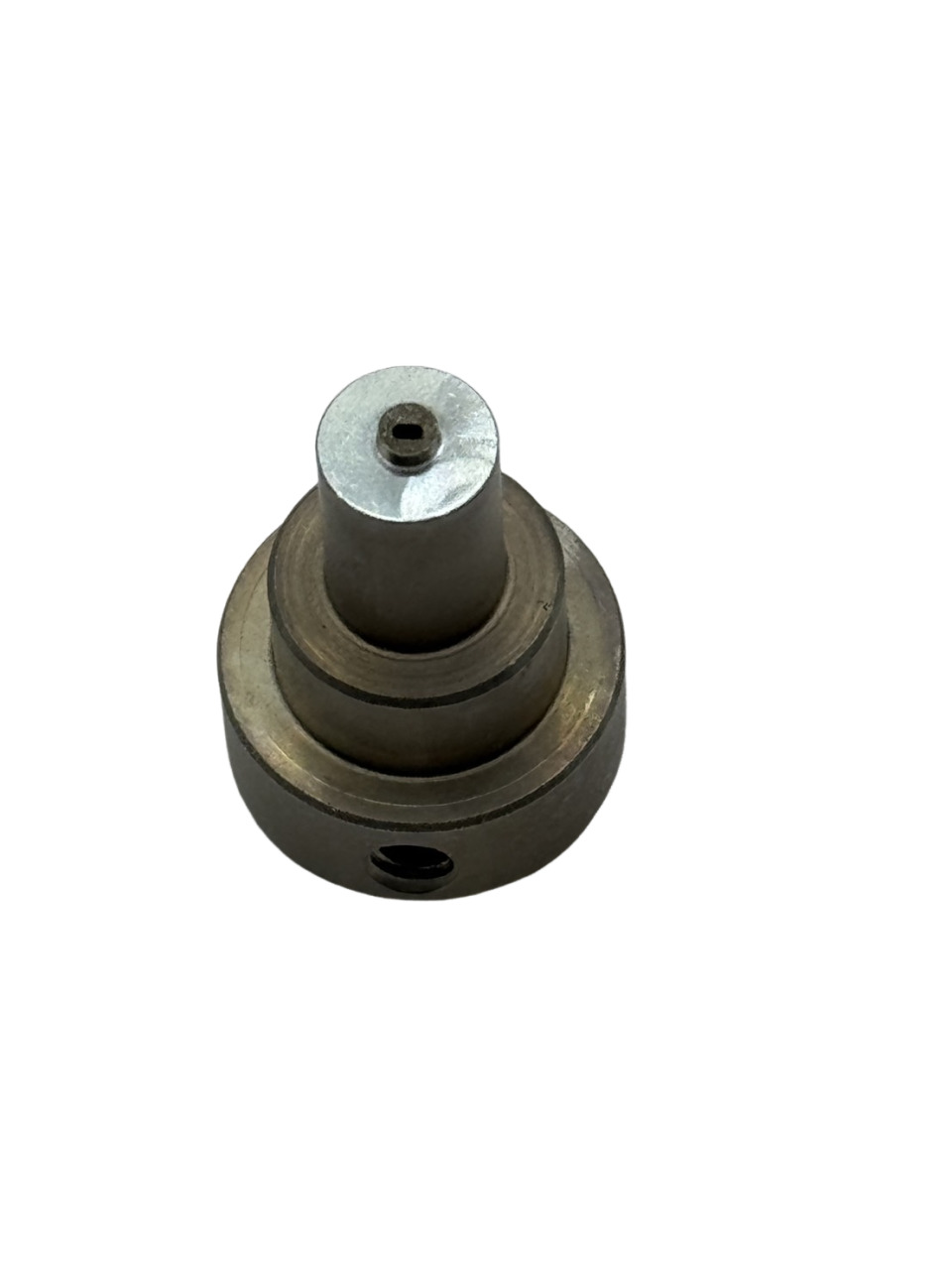
Case Study: We handled a complex part by first using CNC milling for preliminary processing, then using EDM technology to successfully create a precise square-to-round hole transition inside it.

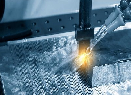
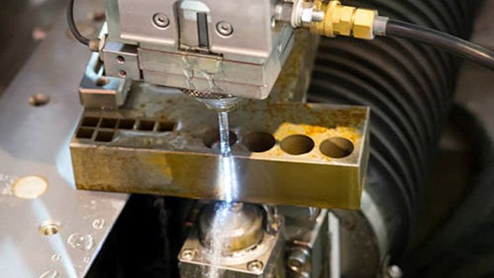
(6) Wire Cut EDM (WEDM)

Wire Cut EDM uses a thin metal wire as an electrode to remove material via electrical spark discharge. This technology is suitable for manufacturing parts from high-hardness materials and with complex shapes.

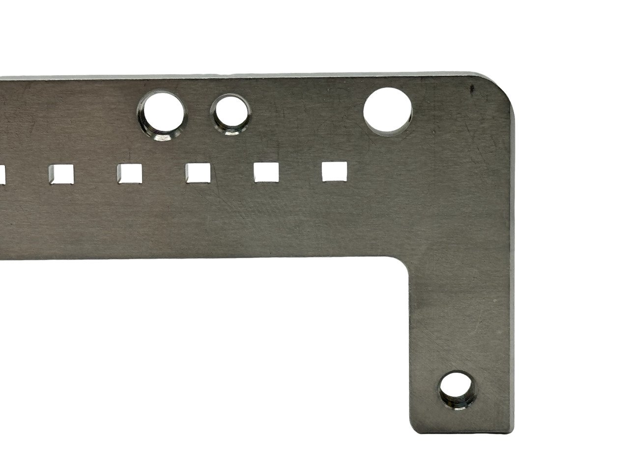
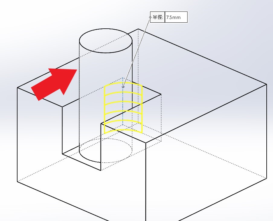
Case Study 1: Our Wire EDM technology was used to create a square hole with an extremely small corner radius (R), while the rest of the workpiece was processed using CNC milling.

Case Study 2: This is a turned part with an elliptical slot smaller than 1mm on the head. We used Wire EDM to create this small slot because standard milling tools cannot achieve such a fine diameter, whereas the thin wire of WEDM can.

Advantages and Applications of Machining

High Precision: Utilizing precise machines and tools, parts can be machined to micron-level accuracy.

Versatility: Capable of processing various metals and plastics to create complex shapes through different processes.

High Customization: Customizing machining processes according to different needs to achieve optimal cost-efficiency.
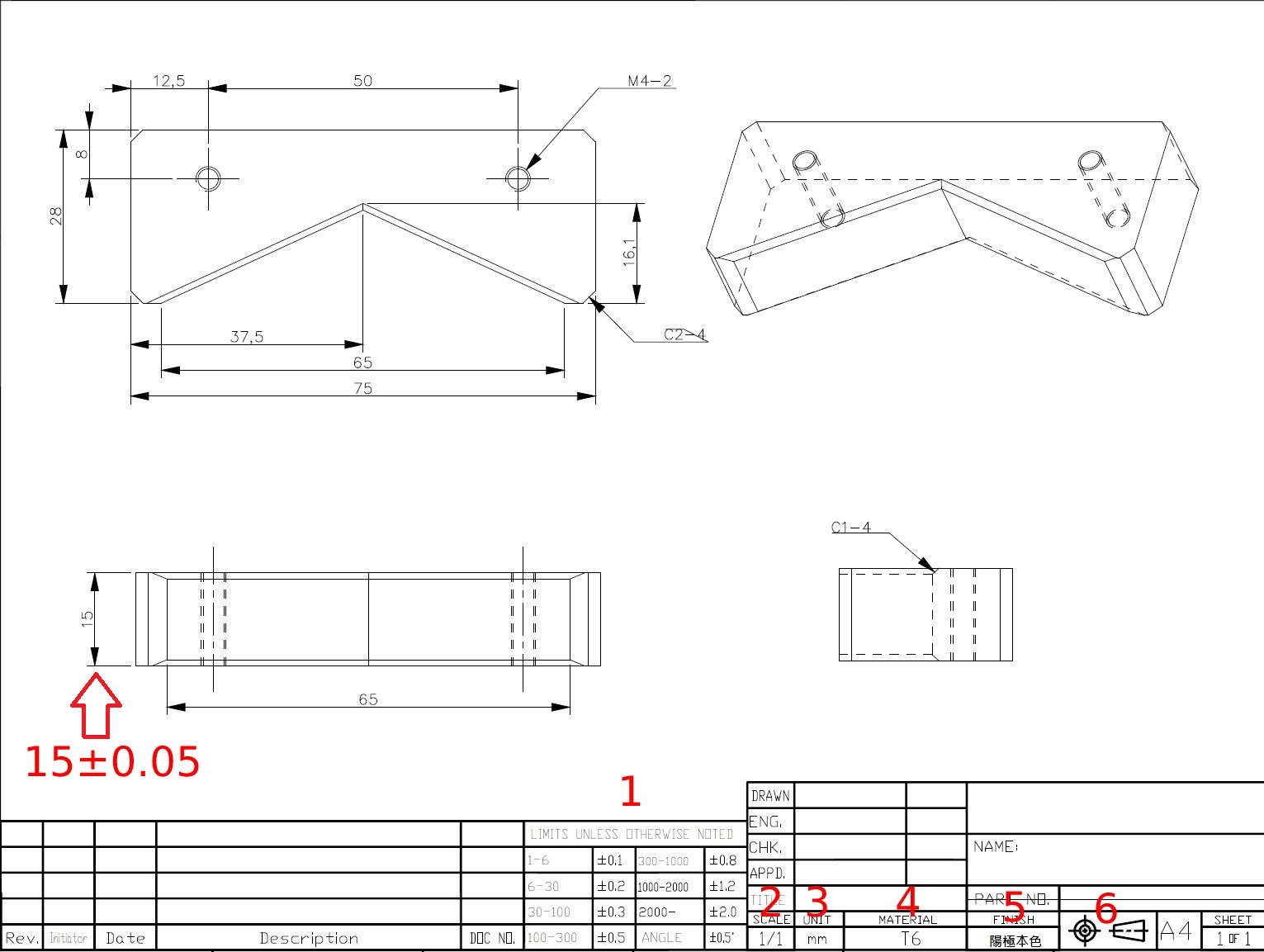
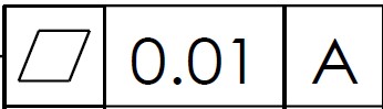
These are the common machining services we provide. If you want to learn more, please contact us. Our professional team will provide you with more detailed information.

Read More

Janway Academy

The Fundamentals of Sintering

Sintering encapsulation involves assembling relevant components into an electronic product, which is then passed to system or module manufacturers for use on circuit boards. Common electronic products include capacitors, inductors, diodes, transformers, relays, and integrated circuits. This article introduces the sintering fixtures for the [Crystal Diode] manufacturing process, an area where our company has extensive experience:

(1) What is a Diode?


Ans: Diodes are often represented by "D" plus a number in circuits, e.g., D5. The main characteristic of a diode is unidirectional conductivity, meaning current passes in only one direction. Under forward voltage, resistance is very low; under reverse voltage, resistance is extremely high or infinite.

(2) Where are Diodes used?

Ans: Due to their unidirectional conductivity, diodes are often used in rectification, isolation, voltage regulation, polarity protection, coding control, frequency modulation, and noise suppression circuits. For example: cordless phones. Different types include Rectifier Diodes (e.g., 1N4004), Switching Diodes (e.g., 1N4148), Schottky Diodes (e.g., BAT85), LEDs, and Zener Diodes.

(3) Diode Structural Types?

Ans: Based on encapsulation, they are divided into Glass Body, Metal Case, Plastic Case, and Epoxy Resin types.

(4) What fixtures are required for Diode Sintering Production?

Ans: Below we use [Glass Body] diodes to explain the fixtures needed in the sintering process.

Since leads, chips (dies), and glass tubes need to be combined during the process, factories producing glass-encapsulated electronics typically use the following fixtures and equipment:

A. Chip Shaker / Die Loading Tray: Selects chips of appropriate electrical properties and size based on the specifications of the glass electronic part. (This stage can also be done by automated equipment instead of manual shaking).

B. Lead Loader & Lead Feeder Box: Arranges leads according to length and size prior to loading into the soldering plate. (This stage can also be automated).

C. Glass Tube Shaker: This fixture arranges glass tubes based on size and length and assists in transferring them to the soldering plate.

D. Soldering Plate (Sintering Boat): Holds the various components in sequence for assembly and passage through the sintering furnace to complete the product.

The fixtures introduced above are essential for producing glass diodes. We hope this article helps you better understand your work and our expertise. Thank you!

[Some images are from the internet; copyright belongs to the original owners]

Read More

Industry Insight - What are Engineering Drawings?

Simply put, engineering drawings use lines and text to precisely express the internal and external structure of an object. Since drafting methods are similar worldwide, engineering drawings are often called the "Universal Language of Engineers." They typically contain plans, sections, and use tolerances to indicate critical areas.

Standard Engineering Drawing Concepts:


*Units and Scale
Engineering drawings typically use mm as the unit of length. If other units are used, they must be noted (e.g., the US uses inches).
*Frame Settings
According to National Standards (CNS), A4 (210*297) / A3 (297*420) borders are typically 10mm. For drawings requiring binding, the left border is 25mm.
*Scale Selection
Scale depends on paper size and part size. Usually drawn at 1:1, but scaled down or up as necessary. Common reductions: 1:2, 1:5, 1:10, 1:20... Common enlargements: 2:1, 5:1, 10:1, 20:1...
*Title Block
The content of the title block varies by organization. Basic items include: Title, Drawing Number, Company Name, Names (Designer, Drafter, Checker, Approver), Date, Projection Method (1st/3rd Angle), Scale, etc.
*Mechanical Projection Methods
First-angle and Third-angle projection are the two main methods, varying by country standards.
First-angle Projection: Most European countries.
Third-angle Projection: USA.
Both used: China, Taiwan (mostly Third-angle), Japan, International Standards (ISO), UK.
First-angle:

Projection plane is behind the object.
Object is in the first quadrant: "Observer" → "Object" → "Projection Plane". First-angle Symbol:
Third-angle:

Projection plane is in front of the object.
Object is in the third quadrant: "Observer" → "Projection Plane" → "Object". Third-angle Symbol:
*Let's look at an actual example:

Nowadays, 3D software is convenient and often includes 3D schematics for easy identification. The dimensions on the drawing allow the machinist to fabricate accordingly. Tolerances are added where parts must mate or fit together, ensuring the machinist pays extra attention to those critical dimensions. For example, if a 15mm thickness has a ±0.05 tolerance, the manufacturing process might differ to achieve that precision.
Bottom right sequence: 1. General Tolerance 2. Scale 3. Unit 4. Material 5. Surface Treatment 6. Projection Angle.

Read More

Industry Insight - Calculating Vacuum Suction Force

A client once needed to calculate if their material could be held by a suction cup of their own design and asked us how to calculate it. After research, we share the current theoretical information:

Calculating the suction force of a vacuum cup requires considering multiple factors, including the cup's size, material, pressure, and the object's weight and surface roughness. The following formula is typically used:

Suction Force (F) = Vacuum Pressure (P) x Suction Area (A)

Where Vacuum Pressure (P) is the pressure difference between the cup and the environment, usually in Pascals (Pa). Suction Area (A) is the contact area, usually in square millimeters (mm^2). For example, if vacuum pressure is 50 Pa and area is 10 mm^2, the force is 500 N. However, this is a rough estimate. For precise calculation, factors like object weight, surface roughness, and cup material must be considered, as they affect the holding force.
Below is our common theoretical suction area table:

Read More

Industry Insight - The Secrets Behind CNC Machining Quotes

Why is the quote for my part so high?

Factory quotes are based on machining time plus raw material costs (variable costs). If equipment depreciation is added, the quote increases. As a customer, you naturally want the lowest cost. If a product is still in R&D, modifying the design to lower machining costs without affecting application can reduce the price.

We offer some concrete directions for reference:

1. Avoid unnecessary right angles
Some right angles (90 degrees) are impossible for CNC milling cutters to produce directly and require corner cleaning or radius relief. Larger radii allow for faster machining. If a sharp right angle is absolute necessary, other methods (like EDM) can be used, but the price will increase. As shown below, a cylindrical milling cutter creating a deep pocket will naturally leave a radius and cannot create a sealed sharp corner.

2. Attention to Tolerance Marking
Part precision relies on tolerance marking. Important areas like mating surfaces, Flatness , or Parallelism require specific processing methods. Marking tolerances is necessary, but marking tight tolerances on non-critical parts drives up costs unnecessarily.
3. Standard Machining Sizes
Most drilling has standard sizes. If a special size like ø2.53mm is used (where decimals aren't multiples of 5), tool costs and quotes will be higher.
4. High Volume
Initial production costs are highest. High volume spreads production costs and lowers raw material costs through economies of scale, resulting in lower quotes.
5. Select Suitable Materials
There are many metal types. For stainless steel, there are 300 series (SUS3xx) and 400 series (SUS4xx). If grinding is required and there are no special conditions, we recommend the 400 series. It is magnetic, making it easier to hold on a magnetic chuck grinder without extra fixtures, lowering manufacturing costs and providing a better price.

Read More

Case Study - Cost Optimization

Client Requirement: A method that meets cost targets while achieving required precision.
Our Solution:

We first ask if cost or precision is the priority. We often find clients prioritize cost, so we suggest the simplest manufacturing method. While this may not meet every tolerance on the drawing, we often discover that certain specified tolerances do not affect their production.

However, in this case, the client was making a high-precision testing instrument, so precision had to strictly follow the drawing, which naturally led to higher costs. After continuous discussion, we provided the most suitable material and processing method to meet their needs, successfully winning the client's approval.

Read More